How to turn your smartphone photos into 3d digital models
One of our current projects with artist, Nisha Duggal, involves stitching together point clouds of interior spaces to create an ‘impossible architecture’. These interiors represent individual spaces and experiences of lockdown. While LiDAR scanners are able to produce high resolution point clouds, their cost is prohibitive for non-specialist users. We wanted to find a way to create point clouds from smartphone camera images to lower barriers to participating in the project. There are a few free photogrammetry options available (e.g. MeshRoom), but most of them are based on CUDA, and therefore require a NVIDIA GeForce graphics card. To make things more complicated, we’re using a 2019 MacBook Pro with an AMD Radeon 5500M GPU, running Mac OS Catalina.
Here, we share our workflow for transforming batches of photos into 3d models using a Mac.
You will need: a subject (e.g. a desk space, or bookcase), a digital camera or smartphone, a Mac with minimum 4GB RAM (larger point clouds require 8GB RAM) and an OpenGL capable graphics card.
This workflow uses the following freely accessible applications: Regard3d, MeshLab, and Unity.
Taking the photos
This is probably the most important step in the whole process. Photogrammetry software works by detecting matching points across multiple images. The camera metadata is then used to calculate and plot the location of those points in three dimensional (x,y,z) space. You need a good set of images with enough matches to create a point cloud.
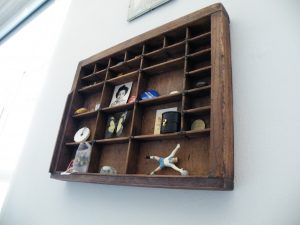
When choosing your subject, be aware large expanses of blank space (e.g. white walls) won’t generate matches. Likewise, transparent objects and moving subjects are unlikely to be picked up. You need a static, well-lit, visually busy or cluttered space, e.g. a work space or bookshelves.
Aim for around 50-80 photos of your subject from different positions, heights and angles. More images are generally better, but too many makes the matching process exponentially slower.
Make sure that each of your photos has at least 50% overlap with other images in the set.
Making the point cloud
Install and open Regard3d: https://www.regard3d.org/index.php/download
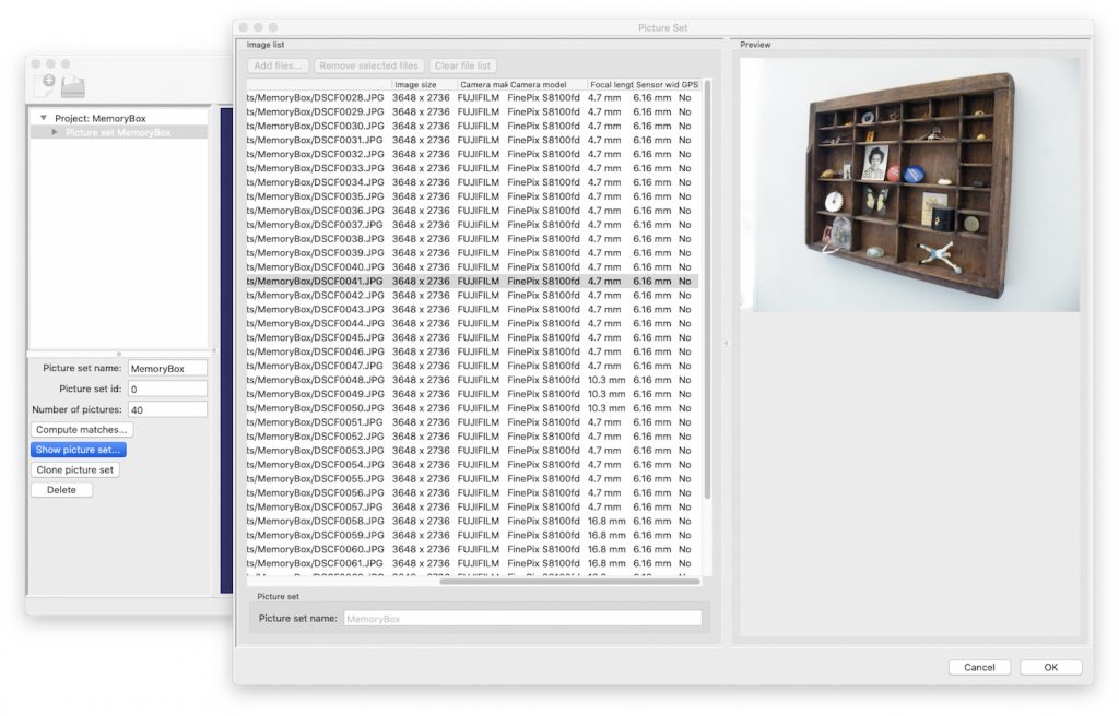
Create a new project and click to ‘Add Picture Set…’
When you upload your photos, the metadata will fill in to the columns on the right. Check this is complete before hitting OK. If your camera is not already in the database, then you may see ‘N/A’ in the sensor width column. In that case, you will need to find out and add the relevant information manually (see how to do this in the notes below).
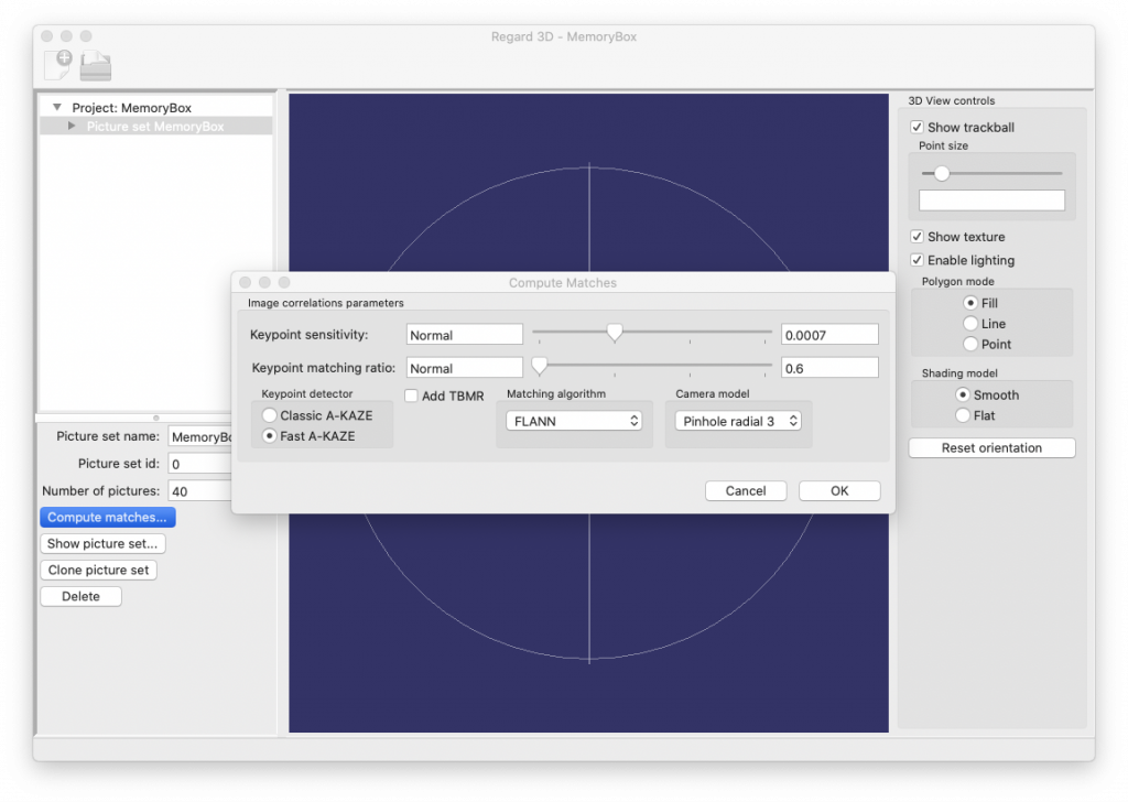
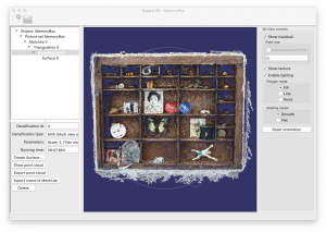
Once the picture set has been added, click on ‘Compute matches’. For decent results with the quickest processing times, use the settings pictured below. For faster processing, slide both sliders to the left. For better matching after running an initial test, select Classic A-KAZE and set the sliders to the right.
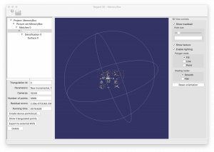
 The next step is to triangulate the matches. With Matches 0 selected in the top left window, hit the ‘Triangulation’ button. Finding the right settings for your project may involve a bit of trial and error. If Incremental Structure from Motion doesn’t yield good results, then manually selecting the initial pair of photos using Old Incrememental Structure from Motion can sometimes work better. For a good starting pair, look for images with a high number of matches taken from different angles. Global Structure from Motion processes matches across the entire batch of photos, but this option will only be available if all images in the set have been taken using the same camera with the same focal length.
You should now be able to see points on the screen, but they may be sparse and unrecognisable, so the final task in Regard3d is to densify the point cloud. Make sure Triangulation 0 is selected and click on ‘Create dense pointcloud’. Again, there are three different tools available, of which we’ve found either MVE (Goesele et al.) or SMVS (Langguth et al.) to produce the best results with smaller photo sets. CMVS (Furukawa) tends to disregard large numbers of pictures, so is better suited to larger scale projects.

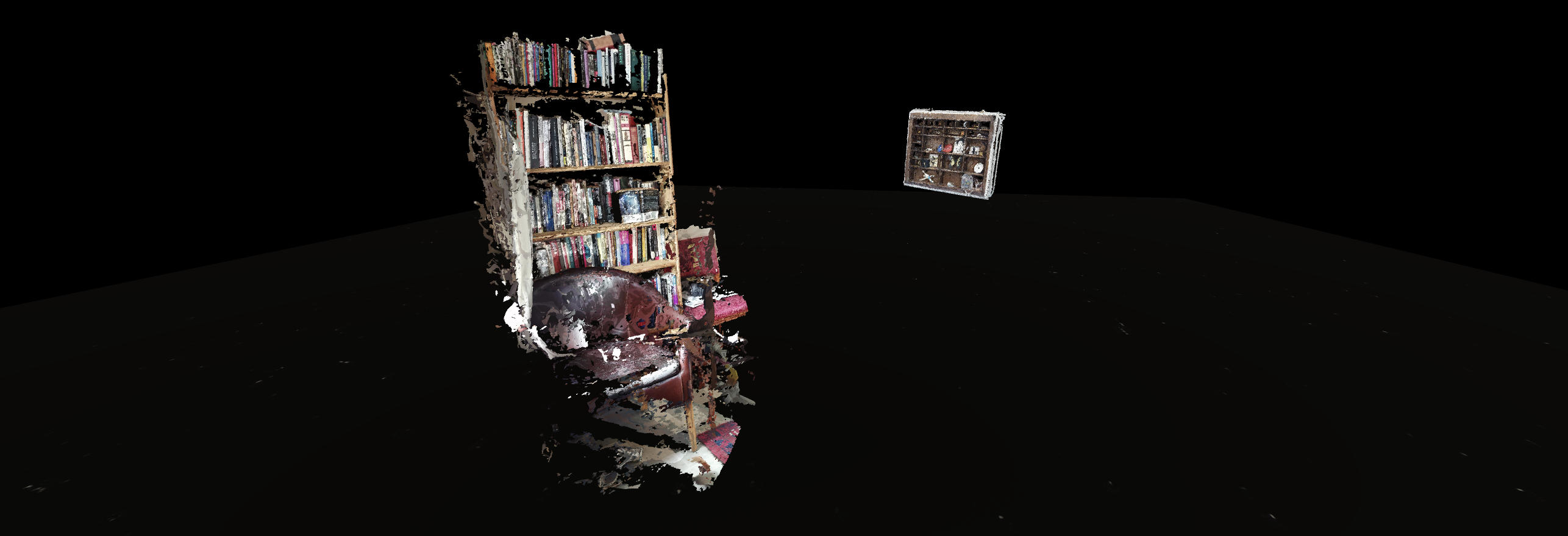
Regard3d gives you the option to create a surface mesh by connecting the points, but for this project, we want to work directly with the cloud. The final step is to ‘Export point cloud’, which saves the selected ‘Densification’ model as a .ply.
Cleaning up the Cloud
Install and open MeshLab: https://www.meshlab.net/#download
MeshLab is a tool for combining, aligning, simplifying and converting point clouds and 3d models for use in a variety of applications, such as 3d printing. There are excellent tutorials for these various features available on the MeshLab site.
For this project, we are looking to delete any unnecessary points and export the point cloud as a binary .ply so that it can be imported into the Unity game engine.
Go to File > Import Mesh, and find the .ply file that you created in Regard3d.
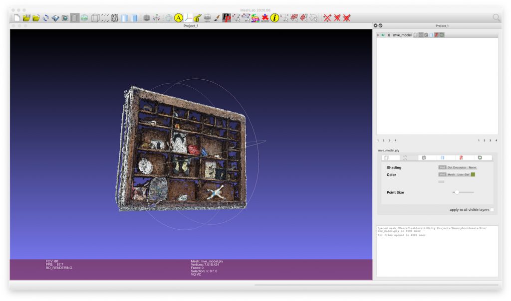

To select points, use the selection tool. If you make a mistake with the selection, there’s no need to deselect. Just click and drag again to make a new selection.

When you are ready, click on the delete button to erase the selected points.
You can click back through your steps in the top right window. When saving, ensure that you have selected the correct version, then go to File > Export Mesh, and check the option for ‘Binary encoding’.
Importing your point cloud into Unity
Unity is a powerful engine for creating 2d and 3d games and immersive environments. It enables you to build an environment using readymade objects, imported as ‘assets’, and to control their physical properties, environment (e.g. lighting conditions) and the user’s experience (e.g. navigation control). There are a range of licenses available, including a free license for personal use.
To download the Unity hub and find out more about subscription options, go here: https://unity3d.com/get-unity/download
We are using Unity version 2019.4.
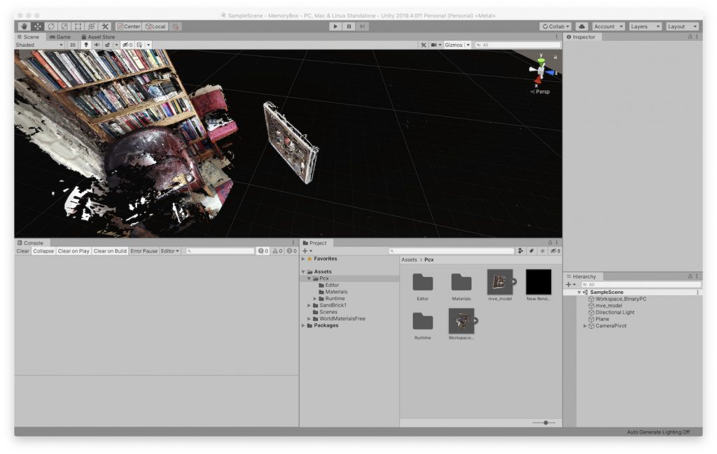
Once set up, you will need to create a new 3d project. Unity does not automatically recognise .ply files, but keijiro wrote the following unity package to import and visualise point clouds using a binary .ply file format:
https://github.com/keijiro/Pcx
Follow the instructions to install the package, then click to unpack within Unity. You should now be able to drag your model into the project assets window to start creating your own impossible architecture!
NOTES:
Updating the User Camera database in Regard3d
If your sensor width doesn’t appear automatically when you import your photo set, you will need to add the information manually. If you go to Options > Edit User Camera DB, the database opens in Regard3d. However, we weren’t able to add the data as expected. If you encounter the same issue, then you may need to locate the .db file in the Regard folder (hit Command+Shift+Dot to reveal hidden folders in Mac OS), and edit it using a database tool such as DataGrip.
It should be relatively easy to find the sensor width for most dslr cameras online. If you are using a smartphone and have trouble locating that information, another option is to install the DevCheck app (iOS/android). The sensor information should be listed under the ‘Camera’ tab.