Introduction
When sensing spatially varying environmental data such as air pollution or air temperature, one option is to employ a mobile sensor, thus avoiding the challenges of deploying an array of spatially distributed static sensors. With a mobile sensor a variety of locations can then be surveyed on foot, or by bicycle or car. However, if a connected sensor system is envisaged, rather than a data logger, then maintaining connectivity involves its own challenges – WiFi is unlikely to offer comprehensive coverage of outdoor spaces and currently LoRa coverage is patchy. Therefore, utilizing the cellular network seems the most viable option.
GSM Modules
There are a variety of cellular breakout boards available, and this example uses a board based on the SIM800L, which are cheap and readily available. This module uses the GSM network and 2.5 G GPRS for data connectivity, which although dated as a technology is still supported on UK cell networks. The SIM800L chip itself requires a power supply of between 3.4 V and 4.4 V and operates at 3.3 V TTL levels. Some breakout boards include an onboard 5V regulator and level shifter so that the module can be driven directly by a 5V microcontroller; other SIM800L breakout boards lack such refinements. In this example we will use a basic module using the latter configuration. A very useful resource for working with the SIM800L mode can be found on LastMinuteEngineers.com here.
Wiring up
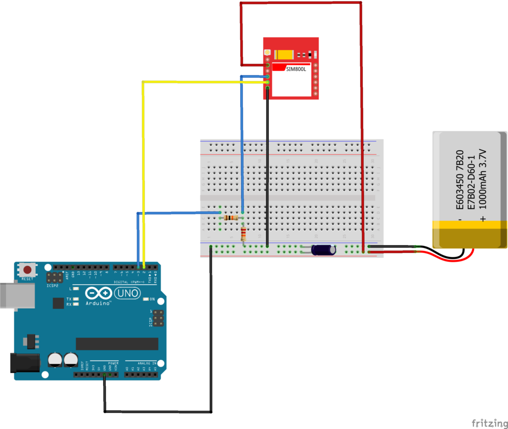
The following schematic is based on the resource mentioned above and uses an Arduino UNO and a basic SiM800L module (without regulator and no level shifter). It uses a voltage divider consisting of a 10 kΩ resistor and 20 kΩ resistor to reduce the Arduino’s Tx level to a level acceptable for the SIM800L. A battery of the appropriate voltage (3.4 V – 4.4 V) is used to power the SIM800L module. A Lithium Polymer battery (nominal voltage 3.7V) with a capacity greater than 1000 mAh is an option, alternatively 3 x NiMH AA batteries (2000mAh) worked well. The capacity of the battery is important as it must be able to supply high burst currents of up to 2 Amps required by the GSM module when transmitting. To aid this a 1000μF capacitor was added across the power rails.

Figure 1 Circuit for a ‘bare bones’ SIM800L GSM Module (i.e. no onboard regulator, no level shifter)
AT Commands
Communication between the microcontroller and the GSM module is via the AT command set and serial communication. Hence the Tx pin of the microcontroller is connected to the Rx pin of the GSM module and vice versa. The relevant AT command set can be found here.
The following commands are a typical sequence to make a HTTP POST request to upload sensor data to a server. The second and third AT commands ensure any previous requests are terminated cleanly.
AT Check connection, should respond OK
AT+CIPSHUT Deactivate GPRS PDP Context
AT+SAPBR=0,1 Close bearer
AT+SAPBR=3,1,”Contype”, “GPRS” Set bearer parameters
AT+SAPBR=3,1,”APN”, “giffgaff.com” Set bearer parameters
AT+SAPBR=1,1 Open bearer
AT+SAPBR=2,1 Query bearer
AT+HTTPINIT Initialize HTTP service
AT+HTTPSSL=1 Set HTTP to use SSL
AT+HTTPPARA=”CID”,1 Set the bearer profile identifier
AT+HTTPPARA=”URL”, “<your-actual-url>” Set your URL
AT+HTTPPARA=”CONTENT”, “application/json” Set content type
AT+HTTPDATA=14,10000 Set POST data length and timeout period
gsmSerial.println(“{\”value\”:25.5}”); Send the payload to upload
AT+HTTPACTION=1 Specify the HTTP method (POST)
AT+HTTPREAD Read the HTTP response
AT+HTTPTERM Terminate the HTTP service
AT+SAPBR=0,1 Close the bearer
Example Code
Some Arduino example code for making a HTTP POST request is shown below. This code use the Arduino Software Serial library to provide the serial communication with the GSM module. The example has been tested by uploading some dummy data to a cloud-based IoT aggregator service (io.adafruit.com).
#include <SoftwareSerial.h>

int TIME_OUT_READ_SERIAL = 20000;

//Create software serial object to communicate with SIM800L
SoftwareSerial gsmSerial(2, 3); //SIM800L Tx & Rx is connected to Arduino #2 & #3


void setup(){
  delay(10000);
  Serial.println("Starting...");
  pinMode(RESET_PIN, OUTPUT);
  digitalWrite(RESET_PIN, HIGH);

  //Begin serial communication with Arduino and Arduino IDE (Serial Monitor)
  Serial.begin(9600);
  initializeGPRS();
}

void loop(){
  testPostRequest();
  delay(100000);
}

void initializeGPRS(){

  //Begin serial communication with Arduino and SIM800L
  gsmSerial.begin(38400);
  while(!gsmSerial){
    Serial.println("Waiting...");
  }
  Serial.println("Connected...");
  sendCommand("AT");
  Serial.println(readSerial());

  sendCommand("AT+CIPSHUT");
  Serial.println(readSerial());

  sendCommand("AT+SAPBR=0,1");
  Serial.println(readSerial());

  sendCommand("AT+SAPBR=3,1,\"Contype\",\"GPRS\"");
  Serial.println(readSerial());

  sendCommand("AT+SAPBR=3,1,\"APN\",\"giffgaff.com\"");
  Serial.println(readSerial());

}


void testPostRequest(){
  sendCommand("AT+SAPBR=1,1");
  Serial.println(readSerial());

  sendCommand("AT+SAPBR=2,1");
  Serial.println(readSerial());

  sendCommand("AT+HTTPINIT");
  Serial.println(readSerial());

  sendCommand("AT+HTTPSSL=1");
  Serial.println(readSerial());

  sendCommand("AT+HTTPPARA=\"CID\",1");
  Serial.println(readSerial());

  sendCommand("AT+HTTPPARA=\"URL\",\"https://io.adafruit.com/api/v2/<username>/feeds/test/data?x-aio-key=<api-key>\"");
  Serial.println(readSerial());

  sendCommand("AT+HTTPPARA=\"CONTENT\",\"application/json\"");
  Serial.println(readSerial());

  sendCommand("AT+HTTPDATA=14,10000");
  Serial.println(readSerial());
  gsmSerial.println("{\"value\":25.5}");
  delay(5000);

  sendCommand("AT+HTTPACTION=1");
  Serial.println(readSerial());
  delay(5000);

  sendCommand("AT+HTTPREAD");
  Serial.println(readSerial());

  sendCommand("AT+HTTPTERM");
  Serial.println(readSerial());

  sendCommand("AT+SAPBR=0,1");
  Serial.println(readSerial());
}


void sendCommand(const char* command) {
  Serial.print("C: ");
  Serial.println(command);
  gsmSerial.println(command);
  delay(1000);
}


String readSerial(){
  long timeOld = millis();
  while (!gsmSerial.available() && !(millis() > timeOld + TIME_OUT_READ_SERIAL)){
      delay(10);
  }
  String str;
  while(gsmSerial.available()){
    if (gsmSerial.available() > 0){
        str += (char) gsmSerial.read();
    }
  }
  return str;
}
The code worked reliably with a 3xNiMH AA battery pack (2000 mAh) but less so when powered by a 1000 mAh Lithium Polymer battery – so you have been warned! The sketch was also tested successfully using a 5V SIM800L breakout board including onboard regulator and level shifter. Somewhat surprisingly, this module could be powered directly by the Arduino UNO 5V pin provided the 1000μF capacitor was added between the power lines to act as a current reservoir. In addition, there are numerous Arduino libraries available for the SIM800L allowing a more elegant and perhaps more robust implementation; these include the TinyGSM libary, GSMSim libary and the Sim800L-Arduino-Library-revised.
Summary
This blog post has explored the use of cheap 2.5G GPRS GSM modules to provide data connectivity for real-time mobile sensor systems. These modules, based on the SIM800L chip, can provide satisfactory results providing proper attention is paid to their transient current demands. It should be noted that although 2.5G GPRS is currently still supported by UK cell networks, it is planned to be phased out by 2033, so projects needing long term longevity should look at 4G-enabled modules, such as those based around the SIM A7670E.

