Introduction
With advances in photovoltaics, low power circuits and communication protocols, it is possible to sustainably power simple indoor sensor circuits via the energy harvesting of indoor ambient light. Indeed, it is now possible to buy commercial indoor environment sensor systems such as the Elsys ERS Co2 LoRa indoor environment monitor that can run indefinitely on harvested indoor light.
The aim of this work was to explore a simple and cheap DIY approach to sustainably powering an indoor connected sensor system, through the harvesting of ambient light. A key design decision was to use a supercapacitor for energy storage. Batteries, even rechargeable ones, have a limited lifetime (charge/discharge cycles) and generally required a dedicated charging IC. Supercapacitors avoid these limitations and although their energy storage capacities are much less than a similar sized battery, they are more environmentally friendly.
LoRaWAN was chosen as the communications protocol, since it is has low power demands on the client and the infrastructure already existed.
Building Blocks
Photovoltaic Panel
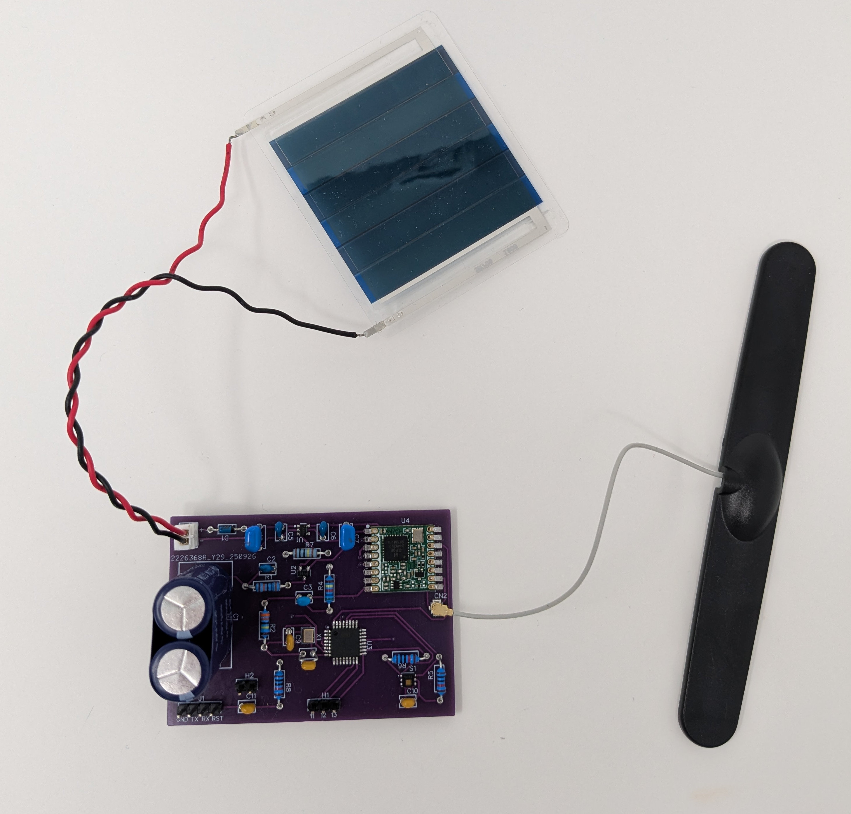
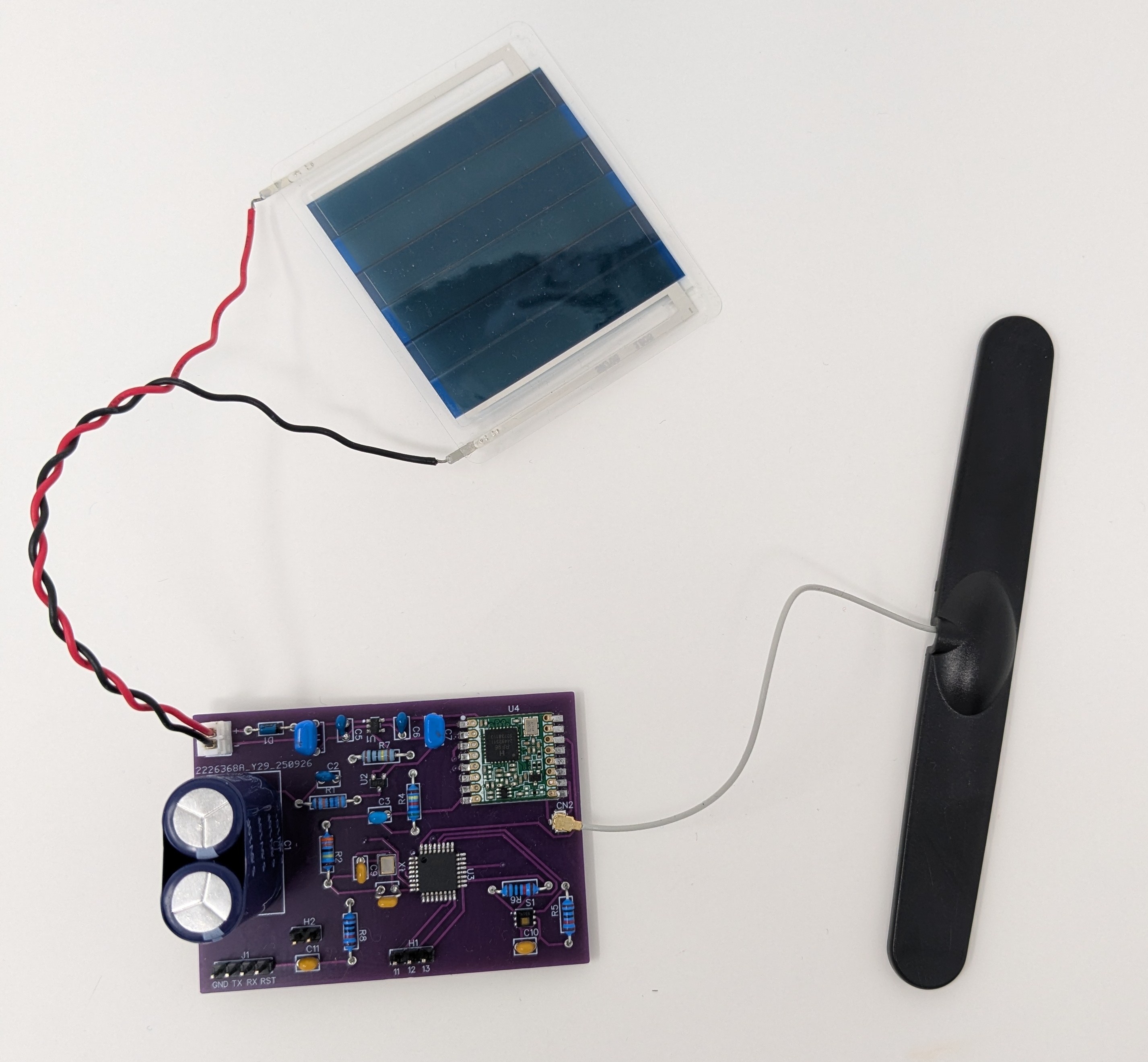
A small 5cm x 5cm organic light harvesting solar panel was used (Epishine LEH3_50x50_6) due to its superior low light performance, compared to conventional silicon panels.
Rectifier Diode
A BAT43 Schottky diode for its low forward voltage drop
Supercapacitor
Abracon 10F 5.5V (ADCM-S05R5SA106RB) supercapacitor. Affordable and high nominal voltage.
Voltage Supervisor
Texas Instruments TPS3839G33DBZR ultralow power, supply voltage monitor. The choice of this component was inspired by this thread. The voltage supervisor disables the system (via the voltage regulator) when the capacitor voltage level falls below the threshold required to reliably operate the circuit. It also adds some hysteresis into the circuit such that the ‘off’ threshold voltage (3.4 V) for a falling capacitor voltage (discharging) is less than the ‘on’ threshold voltage (3.6 V) for a rising capacitor voltage (charging). This ensures that for a rising capacitor voltage the capacitor has a sufficient reservoir of charge to operate the circuit reliably before the regulator is enabled.
Regulator
A 3 V ultra-low quiescent current, low drop out (LDO) regulator (Microchip MCP1711T-30I/OT), which includes an enable/disable pin.
Microcontroller
Microchip Technology ATMega328P-AU. This is compatible with the Arduino platform and the LoRaWAN library required for the LoRa module
LoRa Module
RFM95W which is a cheap and widely available LoRa radio module. The MCCI LoRaWAN LMIC library is used to provide LoRaWAN compatibility.
Sensor
Texas Instruments HDC1080 Temperature/Humidity sensor. Good quality, affordable sensor with low current requirement.
Circuit
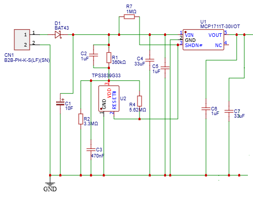
Focusing on the energy harvesting part of the circuit, CN1 is a connector into which the solar panel plugs. The Schottky diode prevents the supercapacitor C1 discharging into the panel when light levels are low. The voltage divider formed by R1 and R2 is used to set the required ‘off’ threshold to about 3.4 V, since the intrinsic threshold of the voltage supervisor is a somewhat on the low side at about 3.08 V. The feedback resistor R4 adds the required hysteresis – the calculation details for determining the appropriate resistor values are documented in a Texas Instruments technical note. With the hysteresis, the voltage supervisor disables the regulator when the rail voltage (the voltage across the supercapacitor) falls to 3.4 V and enables the regulator when the supercapacitor voltage rises to 3.6 V. The hysteresis prevents the system endlessly cycling around the threshold voltage (i.e. the charging capacitor reaches the threshold voltage, the microcontroller starts up and transmits data over LoRa, which discharges the supercapacitor such that its voltage immediately falls below the threshold). The bypass capacitor C2 is critical to correct operation of the circuit, since the voltage supervisor periodically senses the voltage rail using short 200 µS samples that consume a current of approximately 15 µA, sufficient to cause a significant voltage drop across R1 in the absence of the bypass capacitor. The capacitor pairs C4,C5 and C6,C7 provide charge reservoirs to supply the excess current required by the fast transient that occurs when the LoRa radio transmits. R7 is a pullup resistor to ensure the enable pin of the regulator is kept HIGH when not being dragged LOW by the voltage supervisor.
Operation
In general, the prototype worked pretty well in an indoor environment with light levels typically in the range of 500-1000 lux (artificial lighting supplemented by some natural light through windows). For a duty cycle of one transmission every 10 minutes, an average current draw of 115 µA was estimated – assuming a leakage current of 10 µA for the supercapacitor, which is probably a realistic figure. This current draw should be just about sustainable given the prevailing light levels and chosen solar panel. In practice some outages were observed particularly in winter when there was little daylight to supplement the artificial lighting, but the system would restart smoothly once ambient light levels recovered. With a lower duty cycle it is possible the system down time could be avoided altogether. However, it is clear the performance of this simple prototype was not as good as the more sophisticated Elsys system in very low light levels. It is worth noting that swapping out the organic light harvesting solar panel with a much cheaper conventional 0.5 W silicon panel of a similar size made little difference to the performance in a well lit indoor environment, at a considerable cost saving (~ £30 v £3), but would likely not perform as well in dimly lit conditions.
Possible Refinements
There are a number of refinements possible that could improve the performance further. The microcontroller and LoRa radio combined consume about 7 µA when sleeping, which is a satisfactory figure. However, in addition to this, the R1,R2 voltage divider continuously sinks more than 1 µA. And the pullup resistor (R7) will sink perhaps 3.5 µA when the regulator is disabled by the voltage supervisor. Whereas there maybe optimisations possible to the above, it is likely that the largest current drain is the supercapacitor leakage (estimated at 10 µA). One interesting optimisation that the Elsys system employs is a variable duty cycle depending on the supercapacitor state of charge (voltage). This could be implemented, but would require additional components. Another optimisation that would be interesting to explore is using a boost converter to harvest more energy from the solar panel - currently if the voltage across the supercapacitor exceeds that available from the solar panel, then no energy is harvested. However, such optimisations would add additional complexity and cost to the design.